Tuesday, February 10, 2009

Gear shifter assembled

The gear shifter is ready and mounted to the car. The feel was a bit different compared to the old one. Compared to the old one it's very sensitive and accurate.

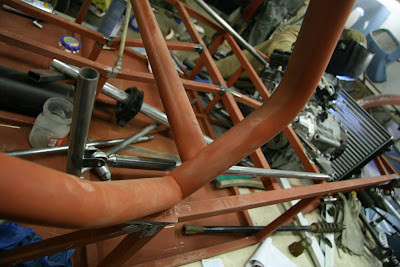
How the shifter linkage attaches to the engine.

Looking forward from the shifter.

The shifter. We will still have to incorporate the "clutch press while downshifting" into the shifter mechanism. This time we will be running with a separate clutch pedal, but we're planning to use it only when driving in the pits or starts.

I ordered dampers and springs from Rally design. This year the starting point will be 450lbs springs at the front and 400lbs springs at the rear. The front will also be stiffened with a anti-roll bar.

Saturday, February 7, 2009

The front suspension mounted, started to make the gear shifter

Lower front suspension coil over mounting point.

Front suspension "assembled".

Gear shifter linkage rocker. The gears are changed this time with rods instead of a tractor push-pull wire. Rocker and gear shifter bearings are commonly available roller skate bearings and the rod-ends are leftover pieces which will do just fine in this application even if they have minimal slop.

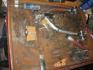
The Ford Taunus spindles after a quick cleaning. The lowest spindle has seized it's outer bearing at some point, a quite usual flaw with these spindles.

Monday, January 19, 2009

Making the first series of front a-arms with the new jig

The first set of front suspension arms is almost ready.
Final adjustments to the jig have been made and both upper a-arms are ready

The lower right a-arm is already mounted
The a-arms are made from cold drawn tubing, so it bends very nicely even with our low cost tools.

The new TIG feels really good.

We also started to make the pedals

Next up is the rear suspension links. As soon as we get the lefthanded 1/2" tap.

Thursday, January 15, 2009

Front suspension jig, more testfitting of the radiator and rear caliper mounts

The radiator seen from inside of the frame. The hoses will have to go in front of the radiator because the hose connections didn't otherwise have enough room. The sides will have to be sealed so air meant to the radiator can't escape from the said

Rear caliper bracket mount.

Measuring the front track width. We are limited to a total width of 1660mm, so using maximum width allowed is important. We are aiming for a couple millimeter under it at maximum camber. The balljoints are from a Ford Transit tie rod. In the picture you can also see the neat aluminium camber adjustment part on the upper a-arm. We got it from ebay.

Front suspension arm jig. The lower a-arm is symmetric, so you can use the same one on the left or right side.

Making of the first front a-arm. The inner tube ends have been welded on and we're waiting for the tubes to cool. After this picture was taken we made a hole on the jig so you could weld both sides of the a-arm without having to rotate it between.

Testfitting the a-arm. We found these tubes from a garbage bin and they have been waiting to be used in some project, this is why they have a couple welds on them.

To the next we'll be making the upper a-arm.

Sunday, December 28, 2008

Finishing the second frame, mounting the radiator and a new frame

1.2 litre -91 Renault clio Radiator. The radiator will be inside the frame. The previous location, inside the nose cone wasn't very good because the radiator is just a little bit too wide. The tube connections on the left side need space, so you need to mount the radiator offset to the left, so our nosecone was pointing a bit to the left instead of being straight. The other benefit is that the radiator is well protected inside the frame.

Fitting the roof tube. We decided to add a diagonal to the roof to protect the driver. Just in case.

Raising the rear of the prop shaft tunnel. We raised it 10cm (4") compared to the previous car. This means we can lower the car to minimum specified ride height (6,5cm or 5.5").

We had made some mistakes when building the frame. Some tubes were wrong compared to the book. We only have work pictures like the one above, nothing of the final connected tubes. I guess while working you don't always have the time to document everything. The "luggage" compartment tubes that we had wrong have also been changed. The series rules are quite specific about that you have to use the book frame to keep every car the same, so no additions or changes to the book tubes can be made.

New frame. Chassis number TT7??FIN (TT standing for my dad's initials). Jari made the frame, and it will quicken the next build quite much. It has a little surface rust because it's been standing outside for quite while.

Tuesday, December 16, 2008

Making the suspension mounting points

Now that we had the frame on the table, we decided to attach the suspension mounting points.

Connecting the front suspension mounts to the frame. The right height was measured with a angle square.

When positioning the front suspension brackeets, we put the car straight compared to the jig table, and then positioned the suspension mounts according to the jig table. In both frames we had a couple millimeters misalignment, and even though the second frame is much better than the first one, the "nose square" is a couple millimeters too much forward on the upper left corner. When we position the suspension brackets according to the jig table, the errors of the frame won't affect the accuracy of positioning the suspension brackets.

Etujousitus työn alla. Korkeus mitattiin suorakulmalla.

Etujousitusta tehdessä meillä on laitettu auto suoraan verrattuna jigipöytään ja jousitus on tehty jigipöydän mukaan. Molemmissa rungoissa on ollut muutama milli heittoa, ja vaikka Mikan runko on parempi kuin eka runko, niin esim. keulaneliö on vasemmasta etureunasta muutaman millin liian edessä. Kun jousitus tehdään jigipöydän mukaan ja mitataan keskelle, saadaan jousituspisteet tarkasti paikoilleen vaikka runko olisikin vähän kiero.

We were very surprised to get the suspension mounts perfectly aligned. Last time we used 10mm threaded rod to align the mounts compared to each other, it wasn't very accurate. This time we had a 10mm steel rod. After welding you could easily push the rod through both mounts and it just felt perfect. We chose rod ends originally because we didn't believe we could align the suspension mounts good enough when using urethane bushings. Using rod ends gives a weight penalty of 3%, but at the time we thought it was worth it.

As you probably notice from the above picture, we did the suspension a bit in the wrong order. In the previous car we did the lower front suspension mounts first, and then the upper ones. Doing the upper ones first means that you have to weld the FU tube in way of the rod so we couldn't perfectly align the suspension mounting brackets.

The rear suspension mounts. We decided to raise them a little so that the rear suspension arms would be level when the car is at the right ride height. I had to check this many times because the difference was so big that it felt just wrong. You can see the old mounting points in the picture.

Thursday, December 11, 2008

New jig table, started to build the second car

We've slowly acquired all the parts for our new jig table and now it was finally time to build it.

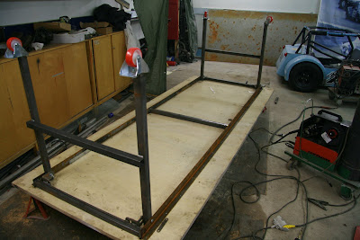
First stage, the jigtable at the floor waiting for supports on the underside.

Mika measuring.

Legs and supports ready.

Legs up!

Supports for the legs. We found the material in a metal recycling trash bin and it's pretty hard stuff. We could only polish the surface with a drill. The easiest way was to weld holes to it.

The number 1 car on the jig table. From the picture you can see the height of the jig table. It's perfect for welding the frame, but a bit too high when welding the upper tubes for the roll cage.

We went through all the welded joints on the frame, and we found a couple that we had missed. We also plugged all the open tube ends.

Saturday, November 15, 2008

Mika came back from the Sema show in the USA with some presents.

Race Technology DL1 with external Lite3 display. Mika decided to get a data logger for his upcoming car and choose the same logger we had in use this summer with a display so he can see his laptimes while driving. Comparing to the old one, it has a different connector at the back and the serial port is moved to the back. The GPS is also a bit more accurate.

Suspension position sensors. Bought them from ebay and I guess these are originally from pneumatic cylinders. They have a motion range of 50mm and weigh a bit more than whats usually used in motorsport, but for the price you can't complain.

We also bought enough rod ends to last for a while. The price is right for imperial rod ends so we decided to change to them from metric size.

Wilwood rear calipers. A nice lightweight package compared to the Volvo 240 series calipers we're currently using.

The cornerscales are shipped by sea, Mika didn't have the space in his bag for them.

Friday, November 7, 2008

Trailer wall, front hub and front caliper

A picture of the trailer wall. It's a structure made from polycarbonate. Two color options available, white and transparent. Heat insulation is of same class as double glass.

We'll be using new parts for the front end.
The hub is machined by Tommis billet in Finland, and they make the front end narrower. Making a narrower hub meant that we don't have as much space for the front caliper as we did earlier, so we needed new ones.
The brake calipers are from Hispec. It took three months to deliver them, even when they promised that they would ship them in two days when I called them. Then it took a couple months to sort out why the calipers costed more than listed in their website. When we got it all sorted out, our first racing season was already over, so we had to buy other brake parts. Good looking parts, but I would probably not buy them again because of the difficulties we had.

We got the dampers of the car sold, and new ones will be according to the newer regulations.

Sunday, October 26, 2008

Testing the gear indicator, removed the shocks

Testing the gear indicator. The display was very simple to install and all sensors came with it. I wanted to test how long the delay is after each gear change but running the engine at idle didn't give a stable enough signal because the sensor only reads one pulse each revolution. I didn't want to run it at higher revs because I was working alone, I'll have to test it some other time. (Had to come up with a good reason why to stop, it was getting quite cold because I had to keep the garage doors open, the garage had already a bit too much exhaust fumes for my liking and the car ran out of battery).

I got the display from ebay from seller bimbembam and I ordered 3 at the same time. This was the only display that I found for a reasonable price

The mounts of the shocks looked a bit bad. Rebound damping anyone? They had either too much load or then they went bad when we pressed in new steel pieces so we could use smaller bolts according to the rules. Either way, we'll have to come up with something that lasts better in the future.

Saturday, October 25, 2008

Locost trailer interior

The first draft for the interior of the trailer. When at the racesite, the back of the trailer will form a bed, in the middle there will be two sofas and in the front there will be the kitchen and storage space. The white square is the space reserved for the door.

A closeup of the kitchen.

When transporting cars the sofas and table will be in the middle of the kitchen with tools and other stuff. The bed has space above the kitchen cabinets.

Friday, October 24, 2008

Locost trailer FEA, part 2

I got the second model ready, and the results are starting to look quite good. I used two different tube sizes for the main frame, and one of them was of course the same 25x25 tube used for the locost frame. The front beam is made of stronger tubing because I didn't have the nerve to make it from anything less. I'm a bit disappointed at the added complexity of the frame, and the final model weighed 230kg.

The picture above shows a situation when two locosts are resting on the trailer. The first model looked quite scary when the displacement was over 50mm at worst, now it's less than 1mm.

Thursday, October 23, 2008

New front cycle wings

A couple photos of our new front cycle wings.

Comparison, old and new wing side by side.

The black color doesn't do the new wing justice, but it looks promising. When we got them I was a bit terrified because their diameter is quite much larger than the wheel of the car, but luckily the gap between the wing and tire doesn't look that bad. We'll also probably make a pair of these on our old trailer.

Tuesday, October 14, 2008

Locost Trailer FEA, the beginning

I got the trailer frame into a FEA program. As always, I had to try to make it the cheapest/easiest way, and of course it wasn't strong enough...


This is a good start, and now I have something to improve on.

Thursday, October 9, 2008

Locost trailer

Were running two locosts next season, so we need something to transport two cars with and a place to sleep and relax during the race events.


Above you can see the first sketch for space inside the trailer. The interior is 7 meters (23 feet) long.

When stationary, the beds will be located above the forward positioned locost and in front of that there will be a living room. At the rear there will be a small workspace and some room for storage.