Sunday, February 18, 2007

February's progress

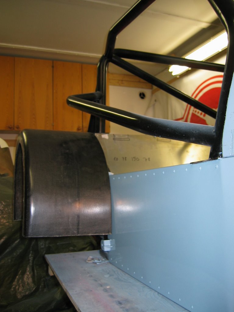
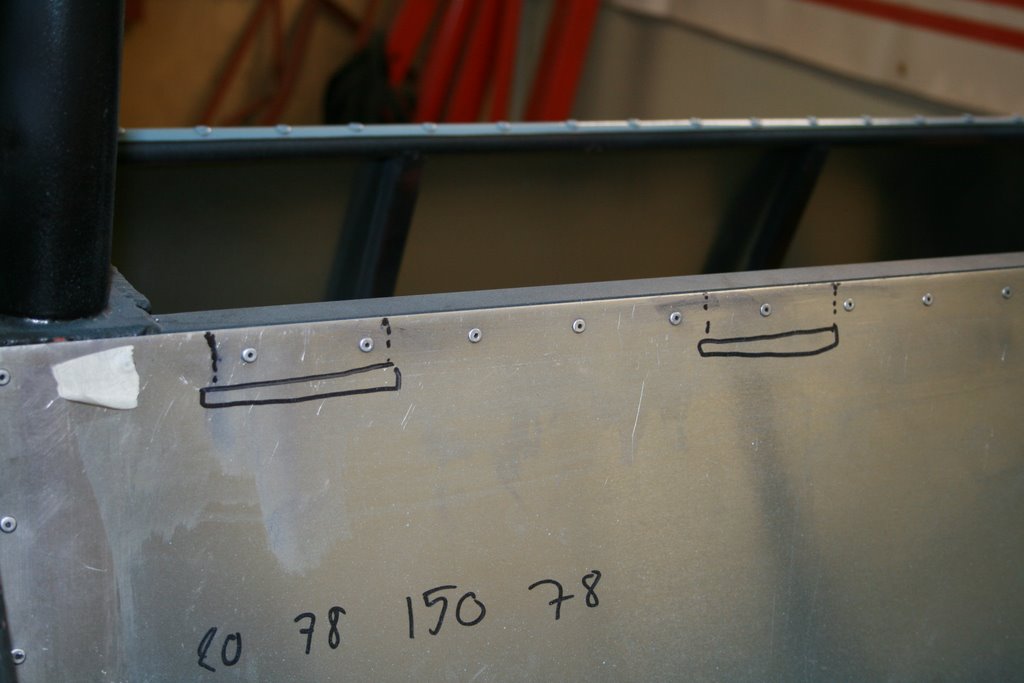
Places for the shoulder harnesses. According to FIA regulations they have to last a force of 14700N per belt. According to calculations just the tube should be enough. This solution was much more lighter than adding a roll cage tube into the trunk area to mount the tubes.

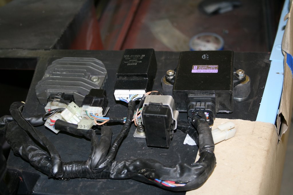
We started to install the engine electrics. The wiring is sorted out and all the components are installed.

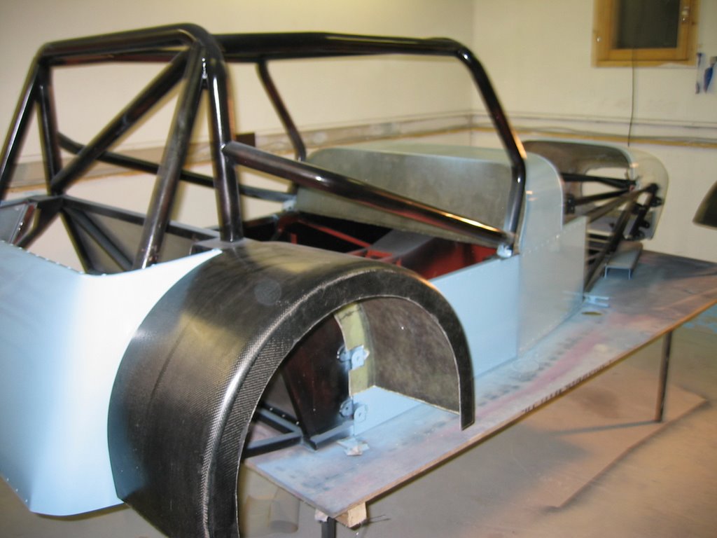
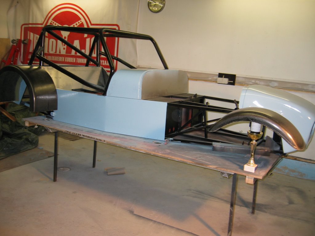
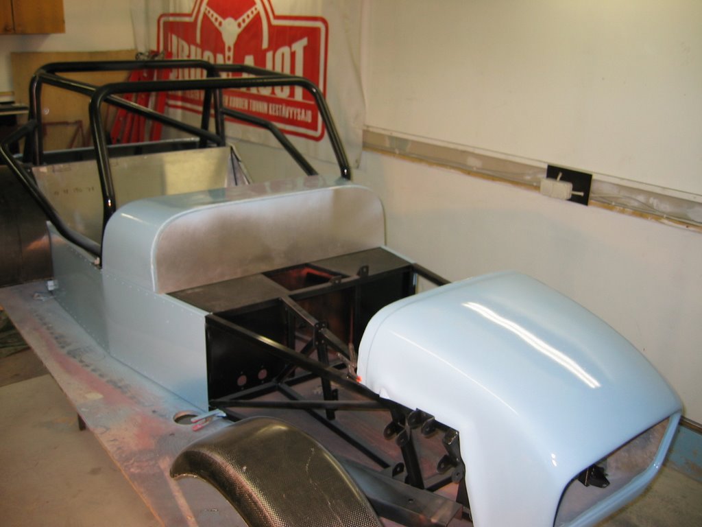
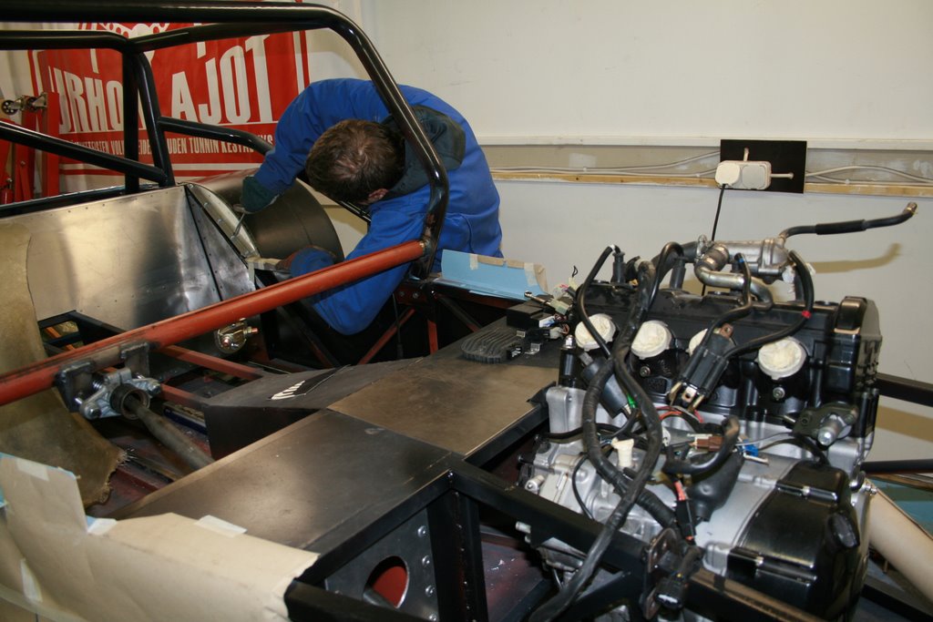
We decided to add a tube to give protection for the driver's feet. There will also be a diagonal brace in the "roof". The steering axle is mounted, main electrical cut off switch is installed and the fenders have been installed.

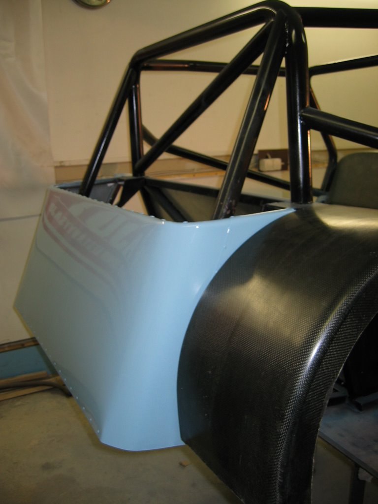
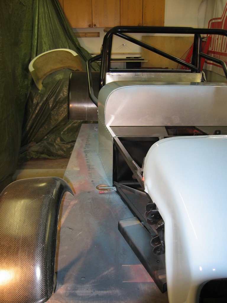
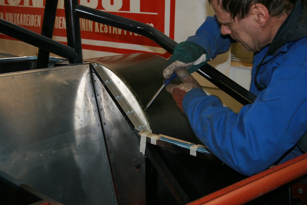
A closer shot of the rear fender mounting. There's also screws on the inside.

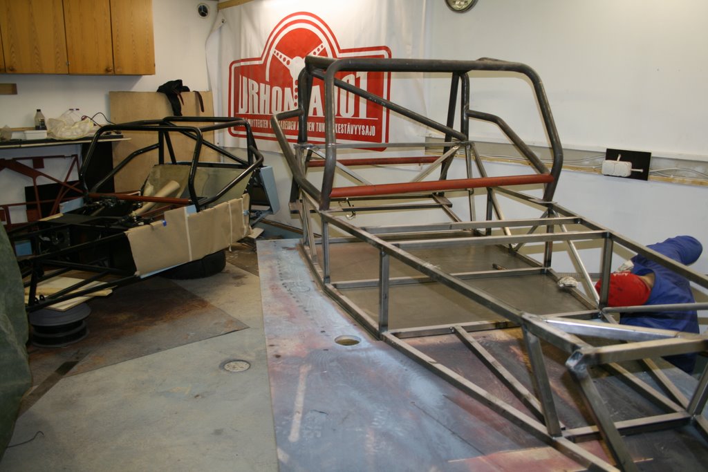
At this point there's so much to design as we build the first car, that when we get resistance or are waiting on parts to arrive it's nice to go to the other car and do the same stuff that we already did on the first.

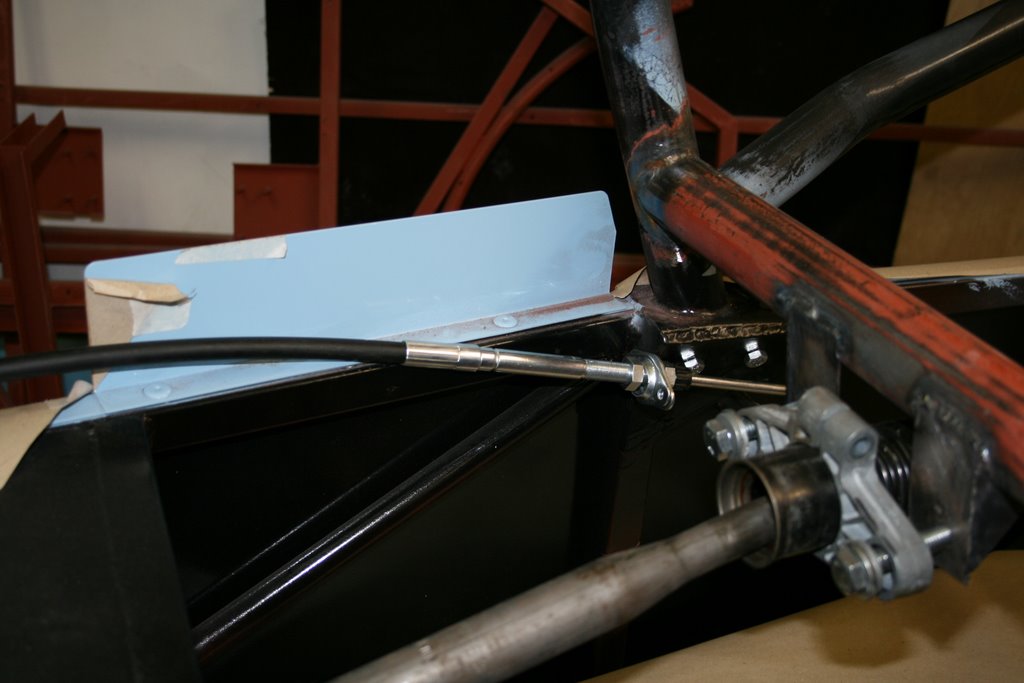
Gearshifter placement. It will be on the right side, next to the roll bar.

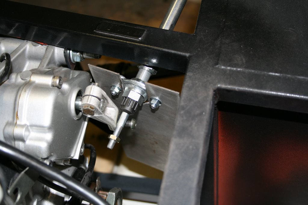
The gearshift cable at the engine end.

(EDIT 2008: This shifter as we installed it isn't advised. The cable made such tight bend that it had enormous friction. It was a bit tricky to shift because the lever didn't move back to the middle position by itself. Also finding neutral was difficult)

Wednesday, February 14, 2007

FEA, frame with roll cage and panels installed

I finally got all panels attached, and the stiffness raised quite dramatically.

The colors show how much the frame twists, red being the highest. Same forces as in the previous pictures.

The torsional stiffness is 4165Nm/deg, which is quite much more than the numbers by Ron Champion (1630-2030Nm/deg). The roll cage brings more stiffness, and the stiffness of the ready frame is usually 15-20% less than that of the calculated.

The frame is as it will be when we build the car, so all wall thicknesses for the tubes are 1,5mm. The floor, firewall and propshaft tunnel is 1,5mm steel when the sides are 1,5mm aluminium.

You can't probably go much higher than 5000Nm/deg if you plan on using the book chassis. Going higher than this would require welding additional tubing, which our racing series doesn't allow.

Analysing the frame made me realize that it was quite simple to make a stiff frame. I had it pretty much as stiff as it can get right from the beginning. What really amazed me how easily you can ruin the stiffness of the car, just removing one of the most critical panels (or making it non-structural by having it removable) can lower the torsional stiffness by 25%!

Friday, February 9, 2007

FEA addition

In the program the color scale being used is pink where there is maximum compression, and blue where there is maximum pull. But it's a bit difficult to get a clear picture of the forces involved because of the scaling. I just found a menu where you can change the colors to make it a bit easier to see the forces. Green shows the lowest forces in the tubes, when red is the highest.

The picture shows the most stressed tubes in the frame when it is being twisted. This picture isn't related to material thicknesses used in the model, it just shows how much force goes through each tube. As you can see the colors in the roll cage are nice and even, so not that much going on there.

The tubes that have to work the hardest are the R tube and the tubes around it on the right side of the engine bay. The triangulated structure seems to take quite a bit load off the left side. If only we would be allowed to have two R tubes. The loads in the prop shaft tunnel tubes should be sorted out once we get the panels added.

FEA, frame with roll cage

Modeling continues

Now the frame twists 1,7 degrees with the same forces as in the previous picture. There is 70% more stiffness compared to without the roll cage. The diagonal in the roof contributes to 30% of the addition in stiffness. The color in the nose says that it twists much more evenly than before, and the roll cage distributes load even to the trunk area.

There's still a little more tweaking with the frame to get the forces to load more evenly. I also figured out how to add the panels, as I thought the mistake I made was very small...

Tuesday, February 6, 2007

3d model is ready for FEA

The wireframe feels ready. I already got to twist a simplified version in a FEA program.


The frame is supported from the upper rear damper mounting points, and it is twisted from the upper front damper mounting points.

I got a stiffness of 936Nm/deg, when Ron Champion says the ready frame should be 1630-2030Nm/deg. At this point adding panels seems a bit difficult, but hopefully it will get sorted quite easily.

Monday, February 5, 2007

First car painted

The team's official photographer got himself so expensive equipment that he can't empty the camera, so I'll have to post some pictures taken with my own :-)


Henrik's car will be baby blue with carbon fenders.


The dashboard is still a work in progress, and the nosecone has a small fault on the other side. Might be that we will have to make a small bulge to the nose cone to fit the radiator. There is two manufacturers for these Renault Clio radiators, and seems like we bought the slightly bigger one.


Moottoritilan peltien sapluunat pitäis kans tehdä piakkoin.


The aluminium for the trunk was made from 1,5mm aluminium, and it required quite a bit of persuasion to get it into form.


Hopefully Henrik will post more pictures very soon!

-Mika