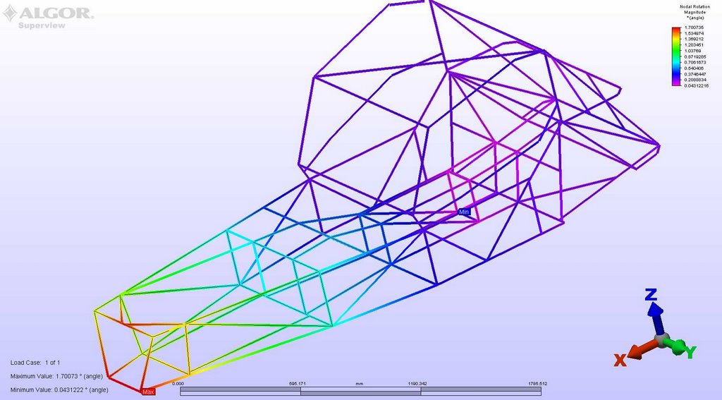
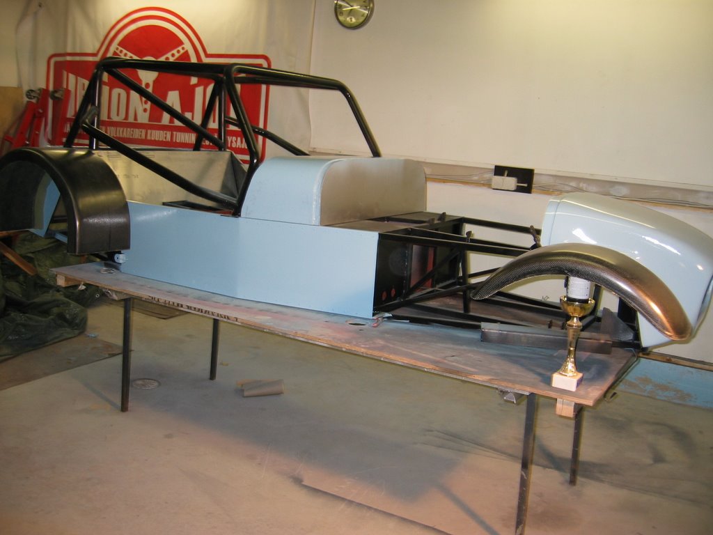
I finally got all panels attached, and the stiffness raised quite dramatically.
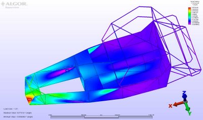
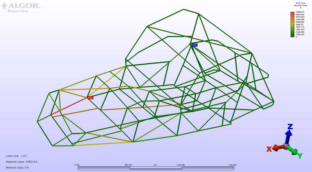
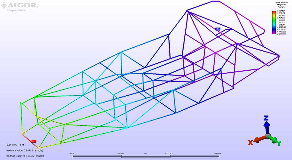
The colors show how much the frame twists, red being the highest. Same forces as in the previous pictures.
The torsional stiffness is 4165Nm/deg, which is quite much more than the numbers by Ron Champion (1630-2030Nm/deg). The roll cage brings more stiffness, and the stiffness of the ready frame is usually 15-20% less than that of the calculated.
The frame is as it will be when we build the car, so all wall thicknesses for the tubes are 1,5mm. The floor, firewall and propshaft tunnel is 1,5mm steel when the sides are 1,5mm aluminium.
You can't probably go much higher than 5000Nm/deg if you plan on using the book chassis. Going higher than this would require welding additional tubing, which our racing series doesn't allow.
Analysing the frame made me realize that it was quite simple to make a stiff frame. I had it pretty much as stiff as it can get right from the beginning. What really amazed me how easily you can ruin the stiffness of the car, just removing one of the most critical panels (or making it non-structural by having it removable) can lower the torsional stiffness by 25%!
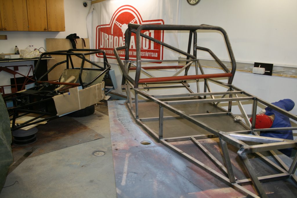
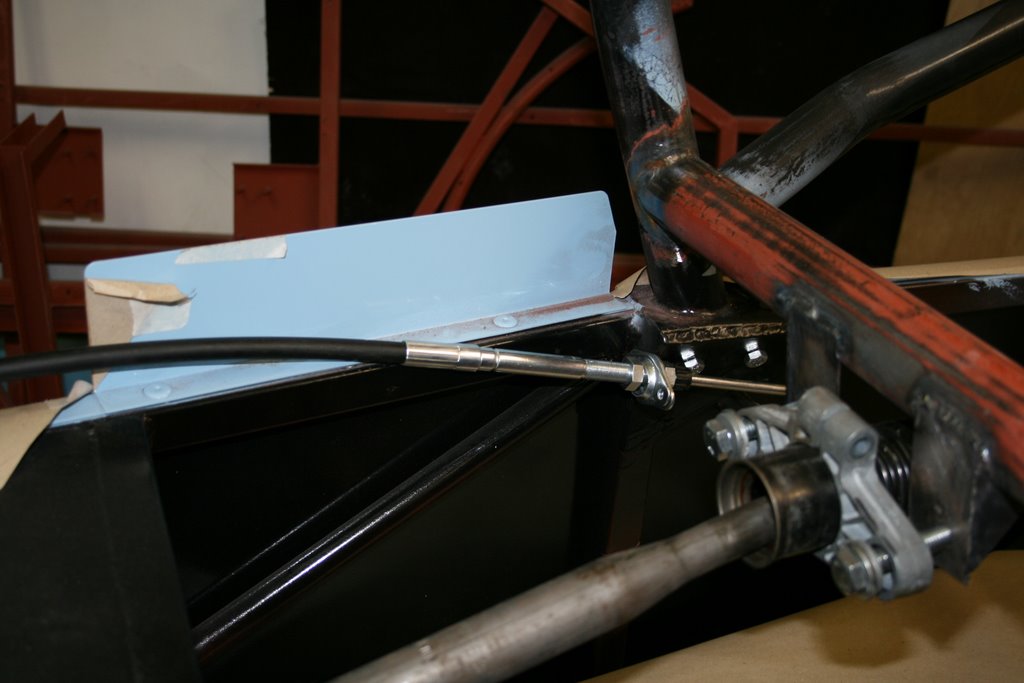
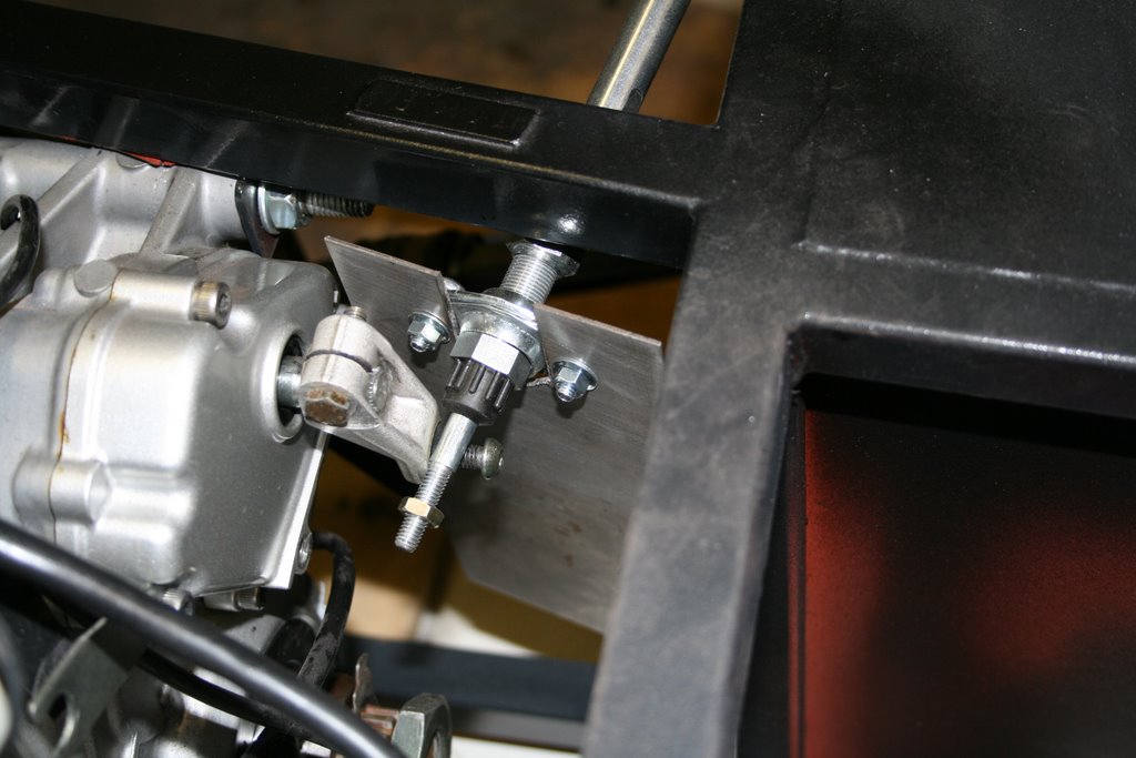
 Revers gear, weight approx. 300g.
 Front end assembled.
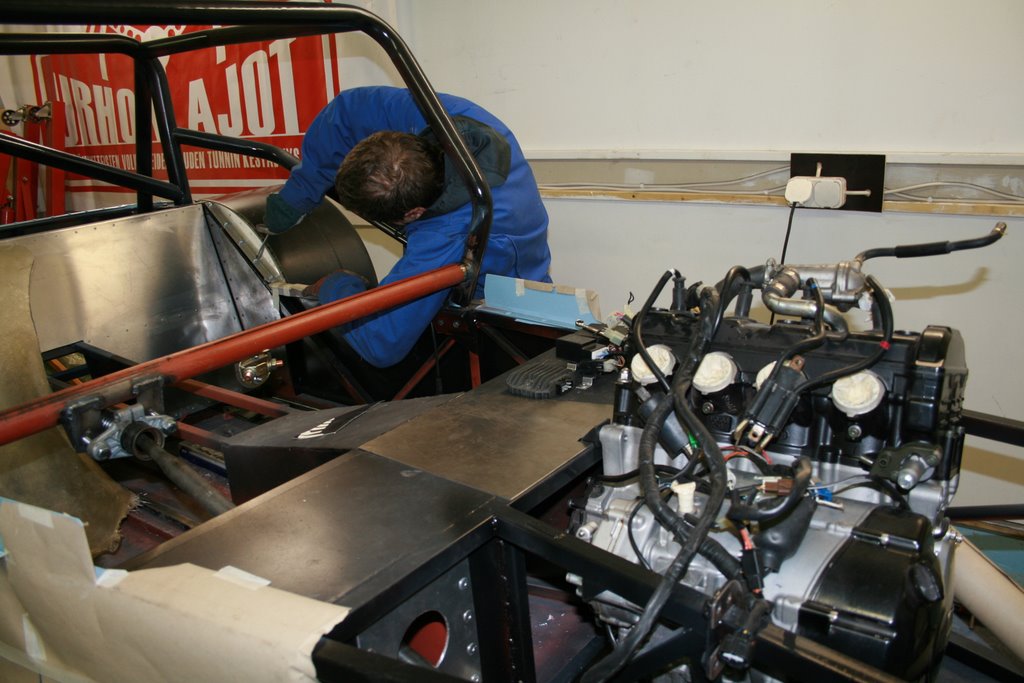
 Making the exhaust...
 Welding the last tube of the header.
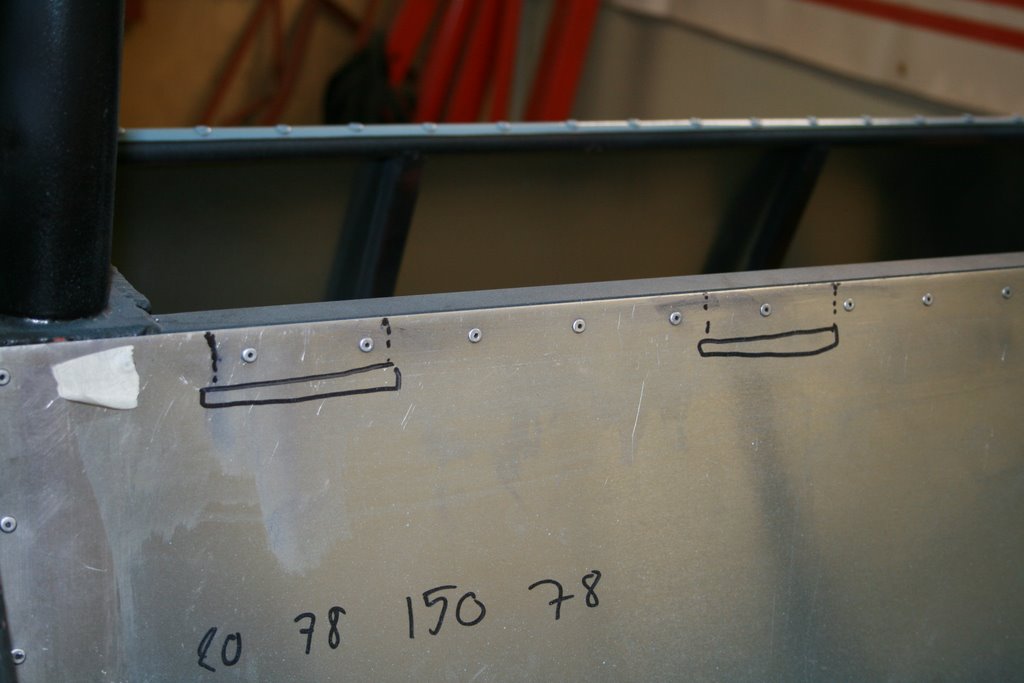
 Fitting the fuel tank. The car will be a twoseater so we can take passengers along for a ride. The fuel tank will be under the passengers knees. The fuel fill we be on the side of the dash.


 "Gelcoated" seat mold. No one told me that gelcoat needs hardener...
 Making the model for the engine cover.
 The cardboard model.
 The cardboard model ready to be cut. The lines were drawn on the inside.
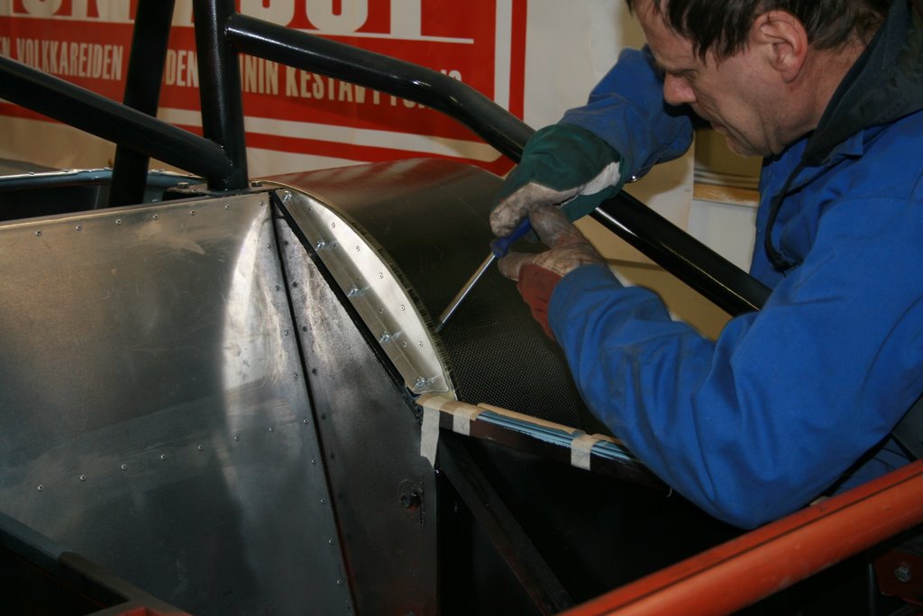
 Bending the engine cover wasn't an easy task. It took three men and a lot of force to get it into shape. Atleast it's stiff.
 Fitting the Lada front disc to the rear axle. The diameter of the mounting flange had to be reduced a bit to make it fit.