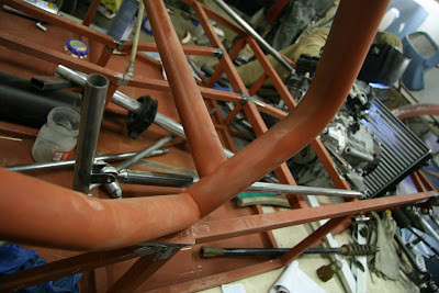
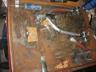
The gear shifter is ready and mounted to the car. The feel was a bit different compared to the old one. Compared to the old one it's very sensitive and accurate.
How the shifter linkage attaches to the engine.
Looking forward from the shifter.
The shifter. We will still have to incorporate the "clutch press while downshifting" into the shifter mechanism. This time we will be running with a separate clutch pedal, but we're planning to use it only when driving in the pits or starts.
I ordered dampers and springs from Rally design. This year the starting point will be 450lbs springs at the front and 400lbs springs at the rear. The front will also be stiffened with a anti-roll bar.
Tuesday, February 10, 2009
Saturday, February 7, 2009
The front suspension mounted, started to make the gear shifter
Lower front suspension coil over mounting point.
Front suspension "assembled".
Gear shifter linkage rocker. The gears are changed this time with rods instead of a tractor push-pull wire. Rocker and gear shifter bearings are commonly available roller skate bearings and the rod-ends are leftover pieces which will do just fine in this application even if they have minimal slop.
The Ford Taunus spindles after a quick cleaning. The lowest spindle has seized it's outer bearing at some point, a quite usual flaw with these spindles.
Monday, January 19, 2009
Making the first series of front a-arms with the new jig
The first set of front suspension arms is almost ready.
Final adjustments to the jig have been made and both upper a-arms are ready
The lower right a-arm is already mounted
The a-arms are made from cold drawn tubing, so it bends very nicely even with our low cost tools.
The new TIG feels really good.
We also started to make the pedals
Next up is the rear suspension links. As soon as we get the lefthanded 1/2" tap.
Thursday, January 15, 2009
Front suspension jig, more testfitting of the radiator and rear caliper mounts
The radiator seen from inside of the frame. The hoses will have to go in front of the radiator because the hose connections didn't otherwise have enough room. The sides will have to be sealed so air meant to the radiator can't escape from the said
Rear caliper bracket mount.
Measuring the front track width. We are limited to a total width of 1660mm, so using maximum width allowed is important. We are aiming for a couple millimeter under it at maximum camber. The balljoints are from a Ford Transit tie rod. In the picture you can also see the neat aluminium camber adjustment part on the upper a-arm. We got it from ebay.
Front suspension arm jig. The lower a-arm is symmetric, so you can use the same one on the left or right side.
Making of the first front a-arm. The inner tube ends have been welded on and we're waiting for the tubes to cool. After this picture was taken we made a hole on the jig so you could weld both sides of the a-arm without having to rotate it between.
Testfitting the a-arm. We found these tubes from a garbage bin and they have been waiting to be used in some project, this is why they have a couple welds on them.
To the next we'll be making the upper a-arm.
Subscribe to:
Posts (Atom)