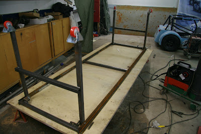
Now that we had the frame on the table, we decided to attach the suspension mounting points.

Connecting the front suspension mounts to the frame. The right height was measured with a angle square.
When positioning the front suspension brackeets, we put the car straight compared to the jig table, and then positioned the suspension mounts according to the jig table. In both frames we had a couple millimeters misalignment, and even though the second frame is much better than the first one, the "nose square" is a couple millimeters too much forward on the upper left corner. When we position the suspension brackets according to the jig table, the errors of the frame won't affect the accuracy of positioning the suspension brackets.
Etujousitus työn alla. Korkeus mitattiin suorakulmalla.
Etujousitusta tehdessä meillä on laitettu auto suoraan verrattuna jigipöytään ja jousitus on tehty jigipöydän mukaan. Molemmissa rungoissa on ollut muutama milli heittoa, ja vaikka Mikan runko on parempi kuin eka runko, niin esim. keulaneliö on vasemmasta etureunasta muutaman millin liian edessä. Kun jousitus tehdään jigipöydän mukaan ja mitataan keskelle, saadaan jousituspisteet tarkasti paikoilleen vaikka runko olisikin vähän kiero.

We were very surprised to get the suspension mounts perfectly aligned. Last time we used 10mm threaded rod to align the mounts compared to each other, it wasn't very accurate. This time we had a 10mm steel rod. After welding you could easily push the rod through both mounts and it just felt perfect. We chose rod ends originally because we didn't believe we could align the suspension mounts good enough when using urethane bushings. Using rod ends gives a weight penalty of 3%, but at the time we thought it was worth it.

As you probably notice from the above picture, we did the suspension a bit in the wrong order. In the previous car we did the lower front suspension mounts first, and then the upper ones. Doing the upper ones first means that you have to weld the FU tube in way of the rod so we couldn't perfectly align the suspension mounting brackets.

The rear suspension mounts. We decided to raise them a little so that the rear suspension arms would be level when the car is at the right ride height. I had to check this many times because the difference was so big that it felt just wrong. You can see the old mounting points in the picture.
 1.2 litre -91 Renault clio Radiator. The radiator will be inside the frame. The previous location, inside the nose cone wasn't very good because the radiator is just a little bit too wide. The tube connections on the left side need space, so you need to mount the radiator offset to the left, so our nosecone was pointing a bit to the left instead of being straight. The other benefit is that the radiator is well protected inside the frame.
 Fitting the roof tube. We decided to add a diagonal to the roof to protect the driver. Just in case.
 Raising the rear of the prop shaft tunnel. We raised it 10cm (4") compared to the previous car. This means we can lower the car to minimum specified ride height (6,5cm or 5.5").
 We had made some mistakes when building the frame. Some tubes were wrong compared to the book. We only have work pictures like the one above, nothing of the final connected tubes. I guess while working you don't always have the time to document everything. The "luggage" compartment tubes that we had wrong have also been changed. The series rules are quite specific about that you have to use the book frame to keep every car the same, so no additions or changes to the book tubes can be made.
 New frame. Chassis number TT7??FIN (TT standing for my dad's initials). Jari made the frame, and it will quicken the next build quite much. It has a little surface rust because it's been standing outside for quite while.


